Dynomotion

Group: DynoMotion Message: 11175 From: j.smilde Date: 3/8/2015
Subject: Multi spindle Biesse Rover 336 with ATC
Attachments :

Hello all!


I am retrofitting a Biesse Rover 336 woodworking CNC machine. It has 3 HSD router spindels with automatic toolchange capebility. The machine has a magazine for 10 tools. The three HSD spindles are offset in the X axis by 160mm each. I am using KMotionCNC 433k with the new tooltable where you can specify a tool  X and Y offset. My goal is to let KMotionCNC/KFLOP compensate/handle the offsets between the router spindles without the cam software knowing of it.


In my setup tools 1..4 are used in spindle 1, they don't have an offset. Tools 5..8 are used in spindle 2, they have a X offset of -160mm and no Y offset. Tools 9 and 10 are used in spindle 3, they have a X offset of -320mm and no Y offset. These offsets are entered in the tool file.


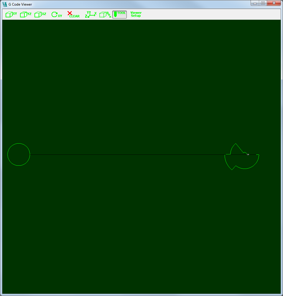
When I run a piece of test code wich mills two equal circles with a diameter of 400mm centered at 0,0 with tool 1 and tool 5 the the G Code Viewer shows the following:

See 2 circles.png


This is my g code:


G21

G0 G17 G40 G49 G54 G80 G90

T1 M6

G43 H1 Z10.

G0 X200. Y0. S12000 M3

G1 Z-10. F2000.

G2 X0. Y-200. I-200. J0. F4000.

X-200. Y0. I0. J200.

X0. Y200. I200. J0.

X200. Y0. I0. J-200.

G0 Z10.

M5

G49


T5 M6

G43 H5 Z10.

G0 X200. Y0. S12000 M3

G1 Z-10. F2000.

G2 X0. Y-200. I-200. J0. F4000.

X-200. Y0. I0. J200.

X0. Y200. I200. J0.

X200. Y0. I0. J-200.

G0 Z10.

M5

G49

M30

%


I would expect to see 2 circles with a diameter of 400mm at the same location.

It looks like the last one is shifted 160 inch and not 160mm.

Can anyone help me out?


Jos


  @@attachment@@
Group: DynoMotion Message: 11176 From: j.smilde Date: 3/8/2015
Subject: Re: Multi spindle Biesse Rover 336 with ATC
Here are 2 video's showing the machine moving and operating the ATC:

Biesse Rover 336 First moves


Group: DynoMotion Message: 11177 From: Tom Kerekes Date: 3/8/2015
Subject: Re: Multi spindle Biesse Rover 336 with ATC [1 Attachment]
Hi Jos,

I'm able to reproduce the issue.  Likely to be an Inch/mm bug on our end.  We'll need some time to investigate.

Regards
TK

Group: DynoMotion Message: 11178 From: bennyattwell Date: 3/8/2015
Subject: Re: Multi spindle Biesse Rover 336 with ATC
i did a rover335 conversion with 3 head setup the same (using mach3)
i used g52 to offset all the heads and drills etc
selecting heads by tool number to make it easy.(handled by m6 macro)
tool1 to 50 =router 1
tool 51-100= router 2
tool 101- 150= router 3
tool 201 first drill etc,  tool 224 last vertical drill.
tool 250 first horizontal drill etc.

all drilling done by 1 macro- the direction etc and offsets controlled by the macro.

i purchased a kflop to do another one, but due to the limited number of i/o at the time never used it.(required 90+ i/o)
i have a 321 biesse the control has done the splits on a month ago. - depending on how well yours turns out i may use the kflop for that one! 
Group: DynoMotion Message: 11179 From: j.smilde Date: 3/8/2015
Subject: Re: Multi spindle Biesse Rover 336 with ATC
Hello Tom, 

Thanks for the fast response!

I think it's not only a mm to inch conversion fault. I switched all settings to inches and this is the result: See '2 circles inch.png'

This is my g code for 2 circles with a diameter of 16inch centered at 0,0
Tool 5 has an X offset of -8inch

G20
G0 G17 G40 G49 G54 G80 G90
T1 M6
G43 H1 Z1.
G0 X8. Y0. S1500 M3
G1 Z-1. F500.
G2 X0. Y-8. I-8. J0.
X-8. Y0. I0. J8.
X0. Y8. I8. J0.
X8. Y0. I0. J-8.
G0 Z1.
M5
G49

T5 M6
G43 H5 Z1.
G0 X8. Y0. S1500 M3
G1 Z-1. F500.
G2 X0. Y-8. I-8. J0.
X-8. Y0. I0. J8.
X0. Y8. I8. J0.
X8. Y0. I0. J-8.
G0 Z1.
M5
G49
M30
%

I am not sure if the X and Y tool offset in the tool file can be used for handling offsets between router spindles on multi spindle machines. (I hope i am wrong!!!!)


  @@attachment@@
Group: DynoMotion Message: 11180 From: j.smilde Date: 3/8/2015
Subject: Re: Multi spindle Biesse Rover 336 with ATC
Hello Benny,

I will look into G52

I reverse engineerd the serial bus for the distuibuted IO modules on my machine.
KFLOP communicates with a XMEGA microcontroller wich in turn communicates with all the io modules. All io's are mapped to virtual io bits wich can be read or set by KFLOP.

I think i have seen some of you're Youtube video's is the machine called Duzit?

Jos
Group: DynoMotion Message: 11181 From: Tom Kerekes Date: 3/8/2015
Subject: Re: Multi spindle Biesse Rover 336 with ATC [1 Attachment]
Hi Jos,

I believe you are correct.  Thanks for the simple example.  2 bugs were found:

Fix Interpreter bug with Tool Table XY Offsets for Arc Endpoint in XY Plane
Fix GCode Viewer bug with Tool Table XY Offsets in Metric

Please try this patch for V4.33k.  Download to \KMotion433k\KMotion\Release these 2 files:

Source code changes are here if needed:

Regards
TK